Single site verification (SSV) is an audit method, where we need to check the entire KPI (Key performance indicator), coverage and quality for a single radio base station site.
For GSM (Global System for Mobile Communications) network a single site
has more than twenty KPI (Key performance indicator), on the other hand for
WCDMA (Wideband Code Division Multiple Access) including HSPA plus a single site has more than forty five Key
performance indicators (KPI). But all the KPI doesn’t carries the same morals,
on the other hand less significant KPI values depends on the major KPIs. So, we often check major Key performance
indicators for single site verification (SSV). The entire single site verification (SSV) can be categorized
into three subcategory.
These are:
-
Radio frequency parameter verification (RF verification).
-
Radio frequency (RF) functionality test.
-
Drive test and RNO (Radio network optimizer)
verification.
Radio frequency parameter audit (RF audit):
RF audit may be classified into parts:- General parameter audit.
-
Radio parameter audit.
General parameter audit:
In general parameter audit, we have to check the
coordinate(latitude and longitude) of radio base station, address, BTS/RBS
information (BTS/RBS name, model or version, vendor etc.), Cluster name and
type, transceiver configuration (TRX
conf), business region name and type, BSC (Base station controller) name, MSC (Main switching center) name, radio base station
security guard or gate keeper contract or house owner contract details.
An example of general parameter audit is given bellow:
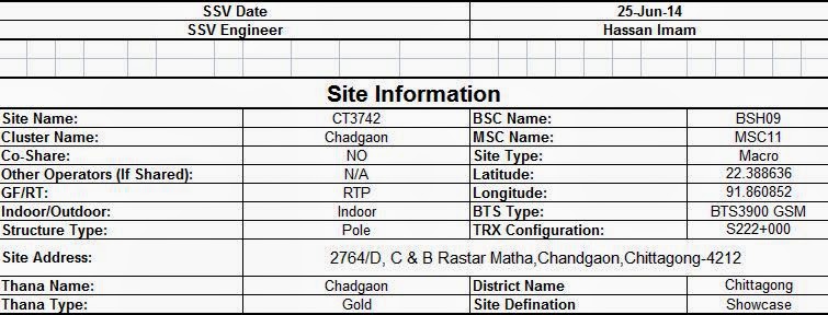 |
| Figure: General radio parameter audit information. |
Radio parameter audit:
In a radio parameter audit, we need to check entire RF parameter such as antenna height, cell azimuth, electrical tilt, mechanical tilt, feeder cable type, feeder cable length, antenna information (model with vendor information), Base station identity code (BSIC), allocated ARFCN (absolute radio frequency channel number) in BCCH (broadcasting control channel), Location area code (LAC) etc.
An example of RF (Radio Frequency) parameters audit is given bellow:
 |
| Figure: Radio frequency (RF) parameter audit information. |
Tools and software for RF parameters audit:
- Digital or magnetic compass.
- Digital camera.
- Tilting meter.
- Fifty meter measuring tape.
- Safety tools for rigger.
- Google Earth (Software)
Drive test and Radio network optimizer (RNO) verification:
Drive test and Radio network optimizer (RNO) verification is
the final step for single site verification (SSV). For SSV drive test we need
to unique arrangement for testing terminals.
Tools and Software for single site verification (SSV) drive test (DT):
- TEMS Investigation data collection software.
Or
- Genex probe
Or
- Nemo outdoor.
- Mapinfo professional (minimum version 8.5scp)
- Microsoft excel (as a SSV template)
Or
- Microsoft Power point (As a SSV template)
- Mobile Station (MS)
- Inverter (as a power source for laptop)
- GPS (Global positioning system) receiver.
 |
| Figure: Drive Test equipment arrangement. |
Drive test (DT) procedure:
Drive test is the most significant
event in entire verification process. For single site verification (SSV) drive
test (DT); we use three mobile stations (MS) as a testing terminal. This Mobile
station (MS) are designated as MS1, MS2 and MS3 respectively. Also we use GPS receiver (global positioning
system) as a testing terminal.
SSV Mobile station (MS) configuration:
Mobile station-1 (MS1):
typically MS1 configured in idle mode and locked with the site.
For locking Mobile station (MS), actually we have to lock Broadcasting
Control Channel (BCCH) for all cell.
Mobile station-2 (MS2):
Typically MS2 configured in
dedicated mode short call and unlocked.
Usually short call duration is thirty seconds. There is no limit of number of
test call. Test call will be continued entire test period with ten seconds as a
frequent call interval period. Redial triggers should be Time out, blocked call
and dropped call.
Mobile station-3 (MS3):
Typically MS3 configured in
dedicated mode long call and unlocked.
Usually, there is no limit for long call duration. Redial triggers should be
Time out, blocked call and dropped call.
 |
| Figure: Command sequence for MS2 and MS3. |
Drive Test (DT) Log collection method:
- · Start collecting log files from the site access road of SSV (Single site verification) radio base site to neighbor site access road, collect the log files in both way, that means from the SSV (Single site verification) radio base site to neighbor radio base site and neighbor radio base site to SSV (Single site verification) radio base site.
- Run the command sequence for mobile station-2 (MS2) and mobile station-3 (MS3), cover the entire car accessible road surrounding (360 degree) of radio base SSV site. Please check the figure in bellow:

Figure: Single site verification (SSV) drive test (DT) route. Drive Test (DT) data presentation System:
Event Analysis:
All the mobile station is significant to check performance of radio base site through Drive Test (DT). We have to present major drive test (DT) event in reporting templates. The major Drive Test (DT) events comprises of number of call attempts, number of call established, call setup success rate (CSSR), number of handover attempt, number of successful handover, Handover success rate (HOSR), number of dropped call and dropped call rate (CDR). The presentation of drive test major event analysis is given bellow:
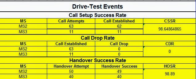
Figure: Drive Test (DT) event analysis
From Mobile Station-1 (Idle mode) SSV data presentation:
From mobile station-1 (MS1), we collect total coverage area of a radio base site and received signal strength (RxLevel) , also we check cell mismatch (feeder cable swap). An example of total coverage area and received signal strength (Rxlevel) of radio base site is given bellow:

Figure: Total coverage area of SSV radio base site. From Mobile Station-2_MS2 (dedicated mode) SSV data presentation:
Form mobile station (MS2), we check basic functionality test, events, handover sequence number (HSN), mobile allocation index offset (MAIO) of radio base site. MS2 functionality test include call setup, call setup time, Inter Site handover, Intra site handover (handover between radio base sites own cell). We have already discussed about event analysis of Drive Test.
From Mobile Station-3_MS3 (dedicated mode) SSV data presentation:
From mobile station-3, we check received signal quality (RxQual), handover relation status (inter cell and intra cell), call continuity, serving cell footprint of SSV drive test route, overshooting of neighbor cell, planning parameter such as ARFCN (Absolute Radio Frequency Channel number) of BCCH (broadcasting control channel).
An example of serving cell footprint diagram is given bellow:

Figure: Serving cell footprint of SSV DT route. RNO (Radio network optimizer) and RNP (Radio network planner) Remarks:
RNP remarks: There is no mismatch found within planned and implemented radio frequency parameter, radio base site coverage footprint is satisfactory.
RNO Remarks: Site performance is satisfactory, Key performance indicator (KPI) monitoring will be continued on daily basis.
Abstract:
ARFCN:
"ARFCN means for Absolute Radio Frequency Channel number. There are 124 ARFCN in P-GSM, 175 in E-GSM, 375 in DCS 1800.
BCCH:
BCCH means for broadcasting control channel, it's a down link channel of GSM air interface. BCCH carries system information of radio base station including available features, configuration and identity.
Call setup success rate (CSSR):
"Call setup success rate is the ration between the number of handover attempts and number of successful handover. CSSR is presented in percentage."
Cell ID:
"Every individual cell of mobile network has a unique cell ID for own network, also there is a cell global identity (CGI). CGI = Mobile country code (MCC) + Mobile network code (MNC) + Location area code (LAC) + cell Id (CI)."
Drive Test (DT):
"Drive test (DT) is a network log collection procedure in vehicular mode."
Drive test (DT) Logs:
" Drive test log files include network signaling and event information; which is collected in real time through Drive Test (DT). Also we can collect logs from the BSC (Base station controller) end through IMEI (International Mobile station Equipment Identity) tracing."
Intra site Handover:
"Intra site handover is the handover between two cell of same radio base site.
Inter site Handover:
"Inter site handover is the handover between two adjacent or neighbor sites cell.
Handover Success rate (HOSR):
"Handover success rate (HOSR) is the radio between number of handover attempts and number of successful handover. HOSR is presented in percentage."
Radio frequency (RF) functionality test:
“Radio frequency functionality test means for checking the various functionality of a single radio base site such as general call test (both long call and short call), call continuity test (long call only), network accessibility test (short call), data throughput test, call setup time etc."
Radio frequency parameter verification (RF verification):
“Radio frequency parameter verification (RF verification) means for verifications of installed radio parameter with the previously planned radio parameter.”

Figure: Received signal quality of entire single site verification SSV of radio base station serving area.


